Getting Rid of the Clatter
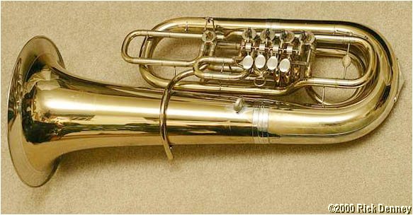
Comes my way: A classic B&S Symphonie F tuba from before the involvement of Perantoni and Tucci to institute the Perantucci line. The B&S dates from the 70's, and despite having old-fashioned clock springs had the first generation of improved linkages over the old S-linkages found on so many old rotary tubas.
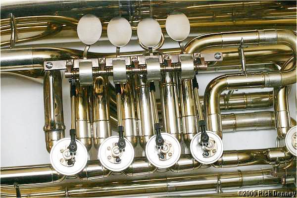
Here's a picture of the instrument:
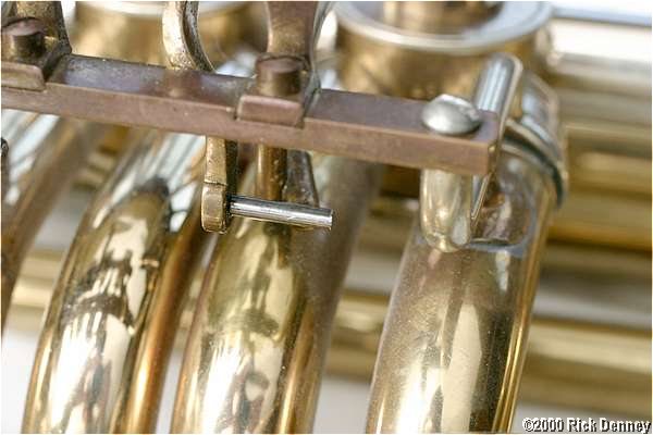
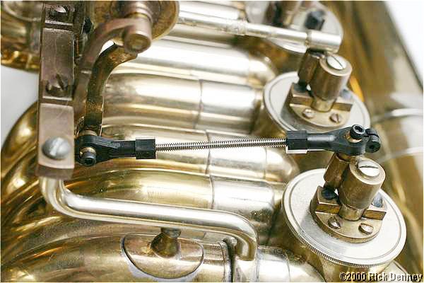
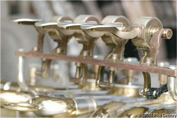
And here's a close-up of the original valve linkages:
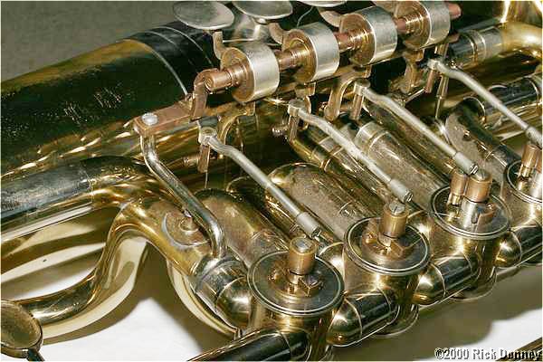
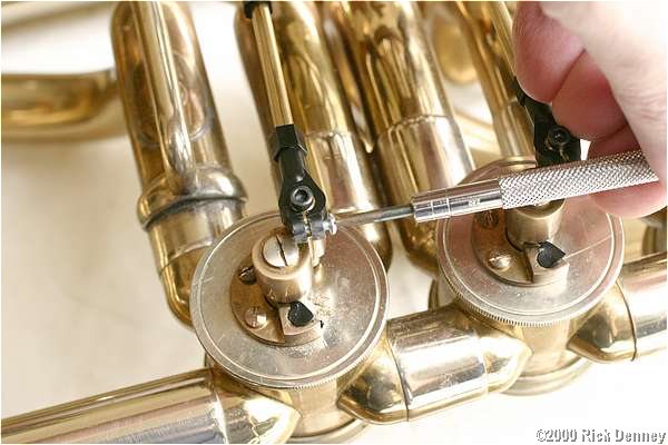
The linkages have the typical pin-in-tube design on the lever end and a newer ball joint on the stop bar. But the ball joints are very small and were worn, plus the first valve pin and tube joint was loose and clattering. Yes, these issues can be repaired, but they will wear again and I decided to do what I'd done on many tubas before, and replace the linkages with modern ball-and-socket linkages using inexpensive parts available at any good hobby shop.
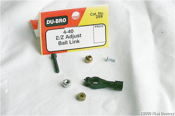
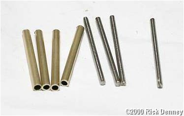
Here are the parts I used:
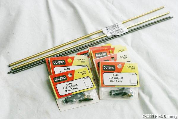
Included are:
- 5/32" Brass tubing. A single foot-long piece is usually enough, depending on the instrument, but two pieces allows mistakes.
- 4-40 Threaded rod. I use the stuff that is continuously threaded.
- Du-Bro EZ-Adjust ball links #259, for 4-40 threaded rod, two for each valve.
I also picked up a 4-40 thread tap, because I'd lost mine, and a handy Allen-head driver that fits the 4-40 socket-head screws that come with the ball links.
The total cost for all of the above was about $25, including the two tools.
The Process
First, I removed the existing linkage on one valve. I used a Dremel tool with a cutoff wheel to grind off the head of the pin that holds the linkage onto the lever.
Once the head is ground off, the linkage will slide off the pin.
Then, I removed the pin. Most of the time, these are screwed into the lever and soldered in place. With a sufficient pair of pliers, they will unscrew.
Sometimes, the solder won't break loose and the pin breaks, as happened on two of the valves I did later in the project. The only recourse is to drill it out. I drill it using the bit that comes with a 4-40 tap, mounted in the flexible-shaft attachment on my Dremel tool.

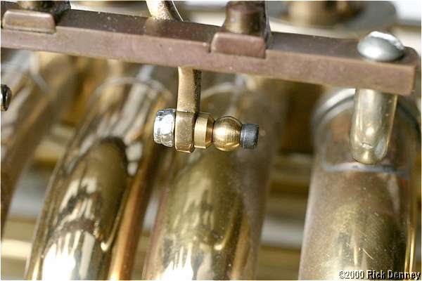
Here are the parts to a Du-Bro ball link kit:
The ball sits atop the brass spacer, and is held in place with the socket-head screw (with nut if needed). The small chrome screw goes into the end of the plastic ball joint to tighten it, though it is really there just to keep the ball joint from popping off if smacked.
Once the pin was removed from the lever, I threaded the ball and spacer through the screw, and then screwed it into the hold left by the pin. With some tubas, the hole may be too big, in which case use the nut. Or, it may be too small, and need to be drilled out. Mine were a hair larger and threaded differently, but it took sufficiently small force to drive the screw into the hole. The nut keeps it from working loose in the future.
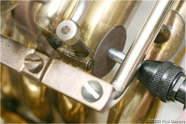
Then, I removed the rest of the linkage by removing the screw at the end so it would slide off the old ball:
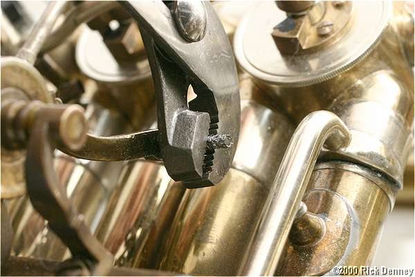
And then I removed the ball, which is screwed into place, using pliers:

I was lucky at this point. The hole in the stop arm was just the right size for the 4-40 bolts, but it was threaded slightly differently. I re-tapped the hole for 4-40 threads:

(Note to repair dudes: A #3 key for winding mechanical clocks fits the square end of a 4-40 tap perfectly, and is easier to handle that the typical tap handle or pin vise. It's about two bucks at a clock shop.)
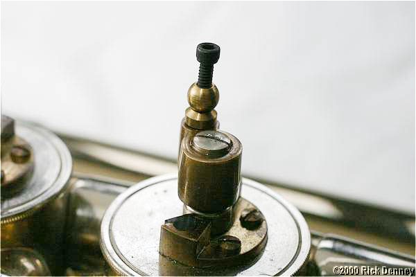
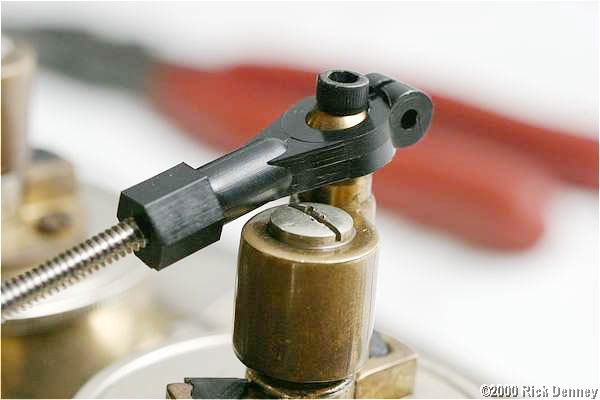
I ran the tap all the way down to the bottom of the stop arm. Then, I blew the bits out and installed the screw, ball, and spacer into the stop arm. Here it is before the screw is tightened down:
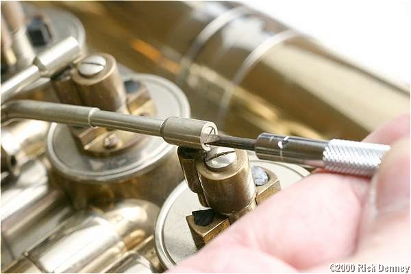
Now, I snap the ball joints over the balls, and then aim them at each other. I've used a rubber-faced clamp to hold the finger paddle at the same height as its neighbor.
With the ball joints in position, I hold the threaded rod up to them to determine where to make the cut. Precision here is not necessary as long as the rod is long enough to be securely screwed into each ball joint.
After cutting the threaded rod with the Dremel cutoff tool, I thread the ball joints onto each end. Note that they are 90 degrees rotated from each other. I also rotate them so that the larger hole for the adjusting screw will face up for easy access (more on that later).
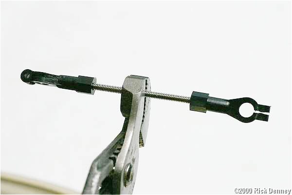
I snap the ball joints back over the balls.
Now, it's time to see if it works. The first thing I check is to make sure the ball joints don't interfere with anything. The typical problem here is the ball joint will contact the stop arm. It's not a problem here, but if it was, I could either carve away a bit of the ball joint, or I could bend the linkage slightly after it's all assembled. But bending it now would preclude installing the brass sleeve. I also have to check to make sure the ball joint doesn't bottom out against the spacer. Again, this is a problem at the stop arm, because the ball joint approaches it at an angle. But the beauty of these ball joints is that precise alignment is not necessary--they can turn in all directions.
Here, I'm checking the other end of the linkage for smooth action:
And here I'm checking that the height of the paddle is the same as the other valves.
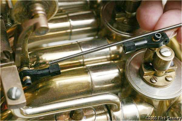
Once I'm sure everything is aligned, I hold up the brass tubing to the linkage to determine where to make the cut. Precision is important here, because it's actually the length of the brass tubing that controls the length of the linkage. I mark the tubing with a Swiss file.
After cutting the tubing using a Dremel cutoff wheel, I check the length. I've nudged the tube into the space between the ball joints, next to the threaded rod. It's tight--and that's how it should be.
Then, I remove the linkage, unscrew one of the ball joints, slip the brass tube over the threaded rod, and then replace the ball joint. The ball joints should tighten down onto the brass tube so that it won't rattle. It's time then to check it once more.
Once one linkage is perfect, I disassemble it and use the parts as masters to make four complete sets of threaded rods and brass tubes.
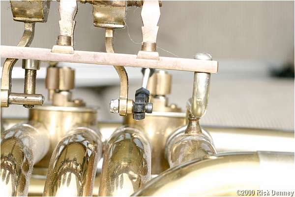
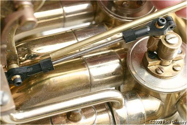
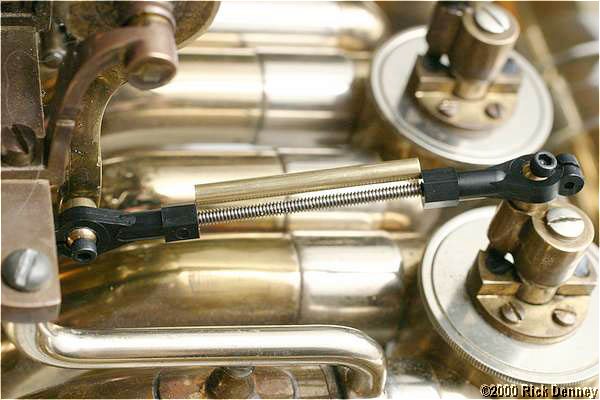
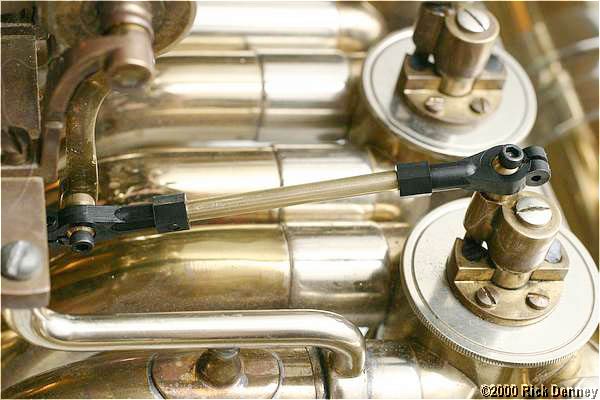
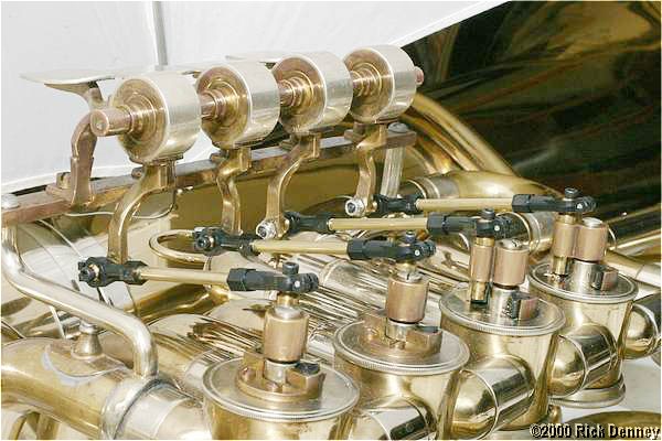
After repeating all the above steps for the remaining valves, I snap all the linkages into place, and check everything for perfect alignment.
Finally, it's time to install the adjustment screw. I tighten it just enough so that it isn't actually tight. It's just there to keep the linkage from getting knocked off. If it is actually tight, it will make the valves feel gummy. I orient the ball joints so that the screws always screw in from the top.
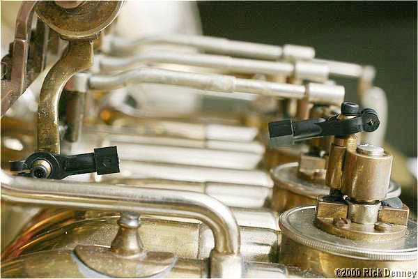
Here are the completed valve linkages. I didn't do the fifth valve--it had too little wear to need it.
I started with the fourth valve, and it took about two hours. Most of that was taking pictures and collecting tools. The other three valves took 45 minutes for all three combined.
To finish up, I put a drop of rotor oil on each ball joint and worked it in. The valve will feel a little different for a week or so until the linkages are fully broken in.